Part 3 of 5 in the LED Walls series
There’s a lot happening behind the scenes to make an LED wall function correctly. Traditional video systems operate within certain parameters and video standards such as aspect ratios, refresh rates, etc. But LED walls are designed from the ground up to be as flexible and creative as possible. Rather than working with predetermined aspect ratios or resolutions, LED panels are generally square, but they can be linked and stacked together to create nearly any design you can imagine. But since each wall can be configured differently, the system requires an engine running in the background that can organize everything. This engine is the LED processor.
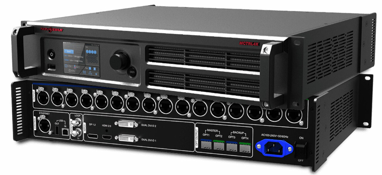
In its simplest form, the LED Processor is the “brains of the operation”. It communicates with the Control Module of each Panel in order to provide information for what each quadrant and pixel needs to do. To start this process, you create a Map or Layout on the LED processor. This tells the processor how many panels are part of the design, how they are connected, and where to begin and end the signal chain. The processor also acts as a Signal Converter - bringing in a broadcast video signal (usually HDMI, SDI, DisplayPort or DVI) and outputting the signal as data using network cables.
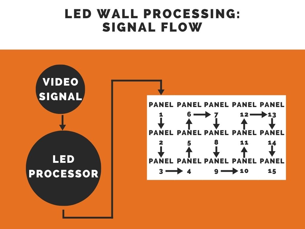
Generally, the signal comes into the first Panel and will loop out to the next Panel in sequence. This prevents each panel from having to be wired directly back to the processor.
However, there are limitations specific to each processor and manufacturer. A processor has a finite number of pixels that it can recreate. In large systems, it is common to use multiple processors in order to get signal to the entire wall. There are also a limited number of physical outputs. Look at the following example:
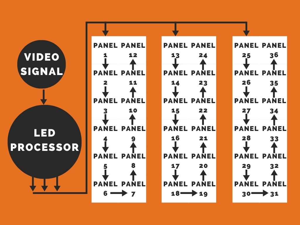
In this design, the LED processor is using 3 Outputs - 1 to feed each group of panels. However, if the processor only has 2 outputs, then either Panel 12 would need to be connected to Panel 13, or Panel 24 would need to be connected to Panel 25.
Each processor also has a total pixel count limit. Theoretically, the wall in the example above may exceed the total number of pixels available on the processor. In that case, a second (or potentially even a third) processor may be required to get signal to the panels correctly.
This article covers signal transmission - getting signal to the panels. However, there is a myriad of additional feature sets to consider before making a final selection. Check out some additional considerations here.
And if you're curious about budgets or pricing, check out our LED Wall Calculator!